Why a DTC is only the beginning of the diagnostic job
A diagnostic trouble code is not a repair instruction. It only tells the technician which control unit detected an abnormal condition. The real fault can be inside the component, in the connector, in the power supply, in a ground point, in a shared reference voltage, in a damaged harness, or even in another module that affects the same circuit.
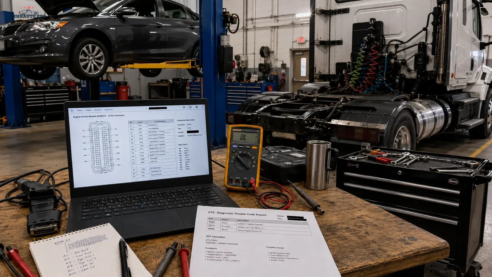
This is why electrical diagnostics should not start with parts replacement. A correct workflow starts with the DTC, then moves to the wiring diagram, connector pinout, measurement points and test results. When these steps are followed in order, the technician can prove the failure instead of guessing.
This guide is written for workshops, mobile diagnosticians and auto electricians who need a practical way to move from a scan tool fault code to a verified circuit test using professional repair data such as WorkShopData Cars or WorkShopData Cars and Truck.
What this workflow is useful for
The method below works for many common diagnostic situations, including:
- sensor signal faults;
- actuator faults;
- open circuit and short circuit codes;
- intermittent warning lights;
- communication faults between modules;
- power supply and ground problems;
- faults after previous repair work;
- no-start and poor-running complaints;
- ABS, airbag, engine, transmission and body control faults.
The exact test values will depend on the vehicle and system, but the structure of the diagnostic workflow stays the same.
Step 1: Confirm the exact vehicle data before opening a wiring diagram
One of the most common diagnostic mistakes is using repair data for the wrong vehicle variant. The same model name can have different wiring depending on model year, market, engine code, emission standard, transmission type and installed options.
Before using any wiring diagram or connector pinout, confirm:
- VIN;
- model year;
- engine code;
- fuel type;
- transmission type;
- body type;
- left-hand drive or right-hand drive layout;
- market version;
- optional equipment that affects the circuit.
This step looks simple, but it protects the technician from testing the wrong connector, wrong fuse, wrong module pin or wrong component location.
Step 2: Save the original scan before clearing anything
The first scan is important evidence. It shows the condition of the vehicle before connectors are touched, modules are reset or faults are cleared. Save the full vehicle scan and keep it with the job card.
The original scan should include:
- DTC number;
- DTC text description;
- module name;
- fault status: current, pending, stored or history;
- freeze frame data if available;
- mileage when the fault was stored;
- battery voltage at the time of the scan;
- occurrence counter if shown by the diagnostic tool.
Do not clear codes too early. When the fault is intermittent, clearing codes can remove the best clue you have. First document the fault, then build the test plan.
Step 3: Read the DTC in context
The same DTC can have different meanings depending on the system. For example, a sensor voltage code can be caused by a failed sensor, but it can also be caused by a missing 5V reference, damaged ground, water inside a connector, short to battery voltage, short to ground or a broken signal wire.
Before testing, ask three questions:
- Which module stored the code?
- Which circuit does the code relate to?
- Is the fault electrical, mechanical, communication-related or software-related?
This prevents the technician from replacing a part when the scan result actually points to a circuit condition.
Step 4: Open the wiring diagram and reduce it to one test path
A complete wiring diagram can be large. The technician does not need to test the whole system at once. The goal is to reduce the diagram to the exact part of the circuit related to the DTC.
Mark the following points:
- control unit name;
- control unit connector number;
- control unit pin number;
- component connector number;
- component pin number;
- fuse and relay path;
- ground point location;
- splice points;
- intermediate connectors;
- wire colors where available.
Once these points are identified, the technician has a usable test route instead of a confusing diagram.
Step 5: Use connector pinout to choose the correct measurement point
The connector pinout is where the diagnostic plan becomes measurable. A pinout tells the technician which terminal should be power, ground, signal, reference voltage, LIN, CAN, sensor output or actuator control.
Do not force large probes into small terminals. Damaged terminals can create a new intermittent fault. Use proper back-probe pins, breakout leads or terminal test adapters where possible.
For every connector test, record:
- connector name;
- pin number;
- expected value;
- measured value;
- ignition state during the test;
- load condition during the test;
- test tool used.
Step 6: Do not rely only on continuity tests
Continuity testing can be useful, but it is often overused. A wire may show continuity with a multimeter and still fail under load. Corrosion, damaged strands, loose terminals and weak ground points can pass a basic continuity test but fail when current demand increases.
For power and ground circuits, voltage drop testing is often more useful than simple resistance testing. For signal circuits, compare the measured voltage or waveform with live data from the scan tool. For communication circuits, use the correct test method for CAN, LIN, FlexRay, Ethernet or DoIP systems.
Practical test examples
| Fault type | Useful test | What the result can show |
|---|---|---|
| Open circuit | Voltage at module pin and component pin | Broken wire, disconnected connector or failed terminal contact |
| Short to ground | Isolated circuit resistance and visual harness inspection | Damaged insulation or water inside connector |
| Short to battery | Voltage test with component disconnected | Crossed wiring or harness damage |
| Weak ground | Voltage drop test under load | Corroded ground point or loose connection |
| Sensor signal fault | Reference voltage, ground and signal comparison | Sensor failure, wiring issue or module input problem |
Step 7: Split the circuit instead of testing everything
If the circuit runs from the engine bay to the dashboard or rear of the vehicle, do not test the entire harness at once. Use the wiring diagram to find an intermediate connector. Test on both sides of that connector.
If the signal is correct before the connector and wrong after the connector, the problem is in that section. If the signal is wrong on both sides, move closer to the source. This method reduces the diagnostic area step by step.
A good technician does not test randomly. A good technician divides the circuit into logical sections.
Step 8: Check service history and previous repairs
Many electrical faults are created by earlier work. Before removing parts, check whether the vehicle recently had:
- body repair;
- engine replacement;
- alarm or tracker installation;
- ECU programming;
- battery replacement;
- water leak repair;
- interior removal;
- towbar or accessory installation.
Previous work can explain damaged wiring, missing grounds, incorrect connector seating or aftermarket wiring connected to the wrong circuit.
Step 9: Document the repair decision
Good documentation protects the workshop and improves future diagnostics. For every electrical diagnostic job, keep a short record of what was tested and what was found.
A clean repair record should include:
- customer complaint;
- original scan report;
- relevant wiring diagram reference;
- connector and pin tested;
- failed measurement result;
- repair action;
- final measurement result;
- post-repair scan;
- road test result if relevant.
This is especially important for intermittent faults. If the vehicle returns later, the next technician can continue from evidence instead of starting again.
Where WorkShopData helps in this process
Repair data is valuable because it gives the technician the information needed to test correctly: wiring diagrams, component locations, connector information, technical data and repair procedures. Without this information, diagnostic time increases and the risk of wrong parts replacement becomes higher.
For passenger car repair data, review WorkShopData Cars. For workshops that also work with commercial vehicles, trucks and semi-trailers, review WorkShopData Cars and Truck.
Final checklist for DTC to pinout diagnostics
- Confirm the exact vehicle before opening repair data.
- Save the original scan before clearing faults.
- Read the DTC in system context.
- Open the wiring diagram and identify the exact circuit.
- Mark module pin, component pin, fuse, relay and ground point.
- Use connector pinout to choose the correct measurement point.
- Test power and ground under load where possible.
- Split long circuits at intermediate connectors.
- Check previous repairs and aftermarket installations.
- Document failed and repaired measurements.
FAQ
Is a DTC enough to replace a sensor?
No. A DTC can point to a sensor circuit, but the root cause may be wiring, ground, reference voltage, connector damage or module input. Testing should confirm the failure before replacing parts.
Why is connector pinout important?
Connector pinout shows the exact terminal used for power, ground, signal or communication. Without pinout information, the technician may test the wrong wire or misread the circuit.
Should I use continuity or voltage drop testing?
Both can be useful, but voltage drop testing is often better for loaded power and ground circuits. Continuity alone can miss weak connections that fail under real operating conditions.
What should be saved after the repair?
Save the original scan, test results, repair notes, final measurement and post-repair scan. This creates a professional record and helps if the vehicle returns later.
A DTC identifies the affected system. A wiring diagram shows the route. A connector pinout gives the measurement point. The repair decision should be made only when the test result proves the fault.